- 您现在的位置:买卖IC网 > Sheet目录1993 > DS1045S-4+T&R (Maxim Integrated Products)IC DELAY LINE 16TAP 16-SOIC
DS1045
3 of 6
DELAY VS. PROGRAMMED VALUE Table 2
PART NUMBER
OUTPUT DELAY VALUE
DS1045-3
9
12
15
18
21
24
27
30
33
36
39
42
45
48
51
54
DS1045-4
9
13
17
21
25
29
33
37
41
45
49
53
57
61
65
69
DS1045-5
9
14
19
24
29
34
39
44
49
54
59
64
69
74
79
84
PROGRAM VALUES FOR EACH DELAY VALUE
A0 OR B0
0
1
0
1
0
1
0
1
0
1
0
1
0
1
0
1
A1 OR B1
0
1
0
1
0
1
0
1
A2 OR B2
0
1
0
1
A3 OR B3
0
1
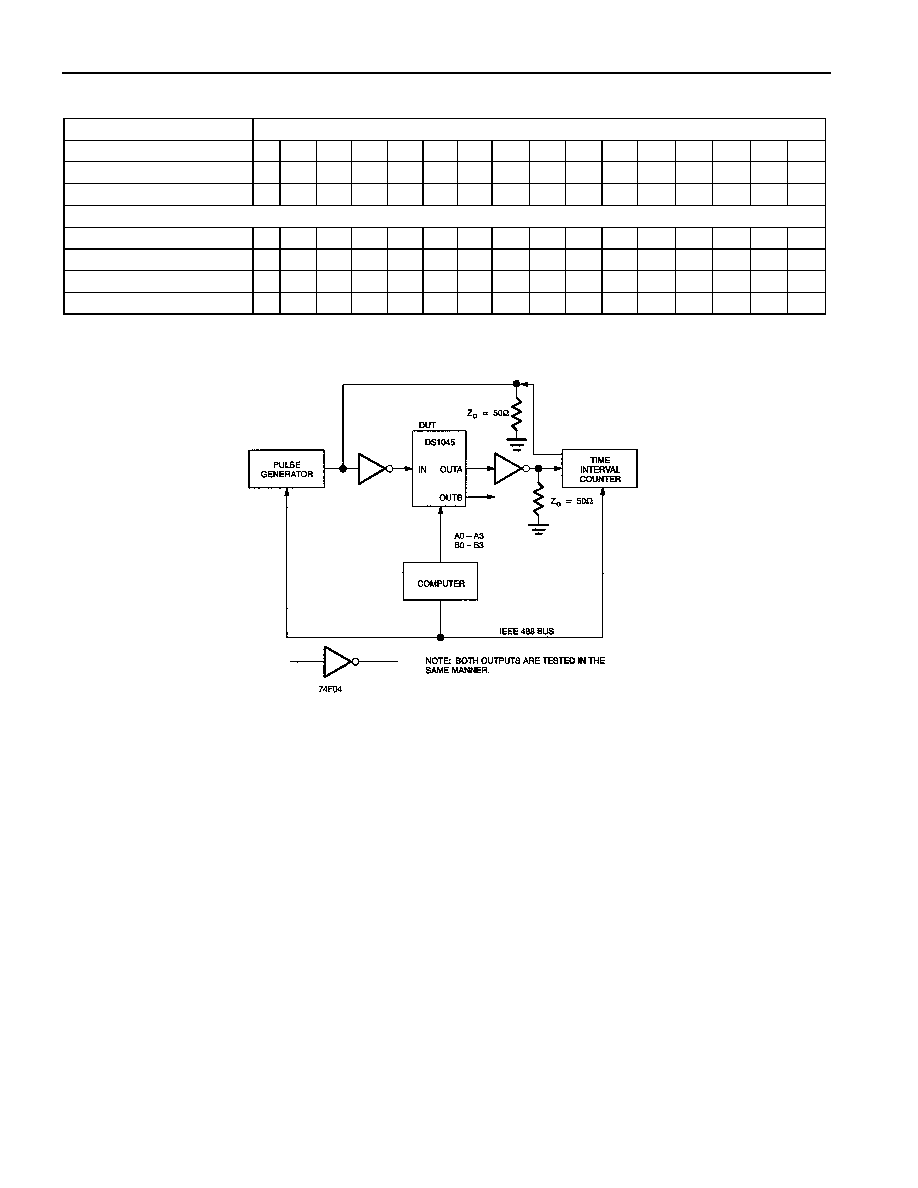
DS1045 TEST CIRCUIT Figure 2
TEST SETUP DESCRIPTION
Figure 2 illustrates the hardware configuration used for measuring the timing parameters of the DS1045.
The input waveform is produced by a precision pulse generator under software control. Time delays are
measured by a time interval counter (20 ps resolution) connected to the output. The DS1045 parallel
inputs are controlled by an interface to a central computer. All measurements are fully automated with
each instrument controlled by the computer over an IEEE 488 bus.
发布紧急采购,3分钟左右您将得到回复。
相关PDF资料
DS1050Z-5/T&R
IC PWM 5-BIT 5KHZ 2-WIRE 8-SOIC
DS1052Z-100+
IC PROG PWM 5BIT 100KHZ 8-SOIC
DS1077LZ-40
IC ECONOSCILLATOR 40MHZ 8-SOIC
DS1077U-120+
IC ECONOSCILLATOR 120MHZ 8-USOP
DS1081LE+
IC CLOCK MOD SS 8-TSSOP
DS1083LR-U+
IC CLOCK MOD SS 3.3V TSOT23-6
DS1100LZ-75+W
IC DELAY LINE 5TAP 75NS 8-SOIC
DS1100M-75+
IC DELAY LINE 5TAP 75NS 8-DIP
相关代理商/技术参数
DS1045S-4+W
功能描述:延迟线/计时元素
RoHS:否 制造商:Micrel 功能:Active Programmable Delay Line 传播延迟时间:1000 ps 工作温度范围: 封装 / 箱体:QFN-24 封装:Tube
DS1045S-5
功能描述:延迟线/计时元素
RoHS:否 制造商:Micrel 功能:Active Programmable Delay Line 传播延迟时间:1000 ps 工作温度范围: 封装 / 箱体:QFN-24 封装:Tube
DS1046
制造商:未知厂家 制造商全称:未知厂家 功能描述:TB motor properties
DS104C2
制造商:TOKO 制造商全称:TOKO, Inc 功能描述:Fixed Inductors for Surface Mounting
DS104LC
制造商:TOKO 制造商全称:TOKO, Inc 功能描述:Fixed Inductors for Surface Mounting
DS1050
制造商:DALLAS 制造商全称:Dallas Semiconductor 功能描述:5-Bit, Programmable, Pulse-Width Modulator: 1kHz, 5kHz, 10kHz, and 25kHz
DS1050-3
功能描述:线性和开关式电源 12V Out 1050W 1U x 2U x 11" RoHS:否 制造商:TDK-Lambda 产品:Switching Supplies 开放式框架/封闭式:Enclosed 输出功率额定值:800 W 输入电压:85 VAC to 265 VAC 输出端数量:1 输出电压(通道 1):20 V 输出电流(通道 1):40 A 商用/医用: 输出电压(通道 2): 输出电流(通道 2): 安装风格:Rack 长度: 宽度: 高度:
DS1050-3-001
制造商:Johnson Components 功能描述:AC/DC Power Supply Single-OUT 12V 87A 1.05KW 34-Pin